Project Overview
This project presents the design and control of a fully 3D-printed quadruped robot with 8 degrees of freedom (2 per leg). Built on an Arduino microcontroller platform, the robot integrates mechanical design, embedded systems programming, and advanced control algorithms to achieve stable locomotion across various terrains.
The robot serves as a research platform for future study in legged locomotion, demonstrating the practical implementation of inverse kinematics, gyroscope-based stabilization, and gait generation algorithms. Future integration of ROS and MuJoCo-trained reinforcement learning models will enable adaptive locomotion across diverse terrains.
Key Features
- Fully 3D-printed mechanical structure
- 8-DOF actuation system with MG995 servo motors
- Real-time balance control using WT901CM IMU and PID algorithms (In Progress)
- Forward and inverse kinematics for precise leg positioning
- Wave function-based gait generation for coordinated walking
Locomotion Demonstration
Current Control Algorithm
Joint angles are computed using the inverse kinematics simulation described in later sections. Pre-calculated trajectories are loaded onto the Arduino to minimize onboard computation, and PWM signals are sent to the eight servos at a 20 Hz update rate.
Design and Fabrication
CAD Modeling
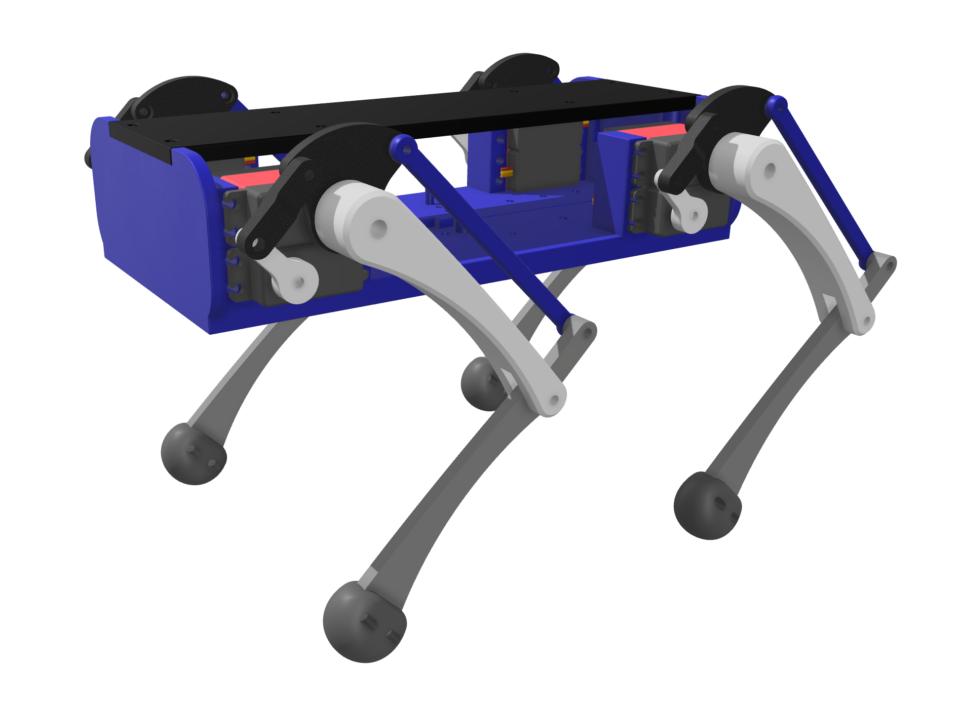
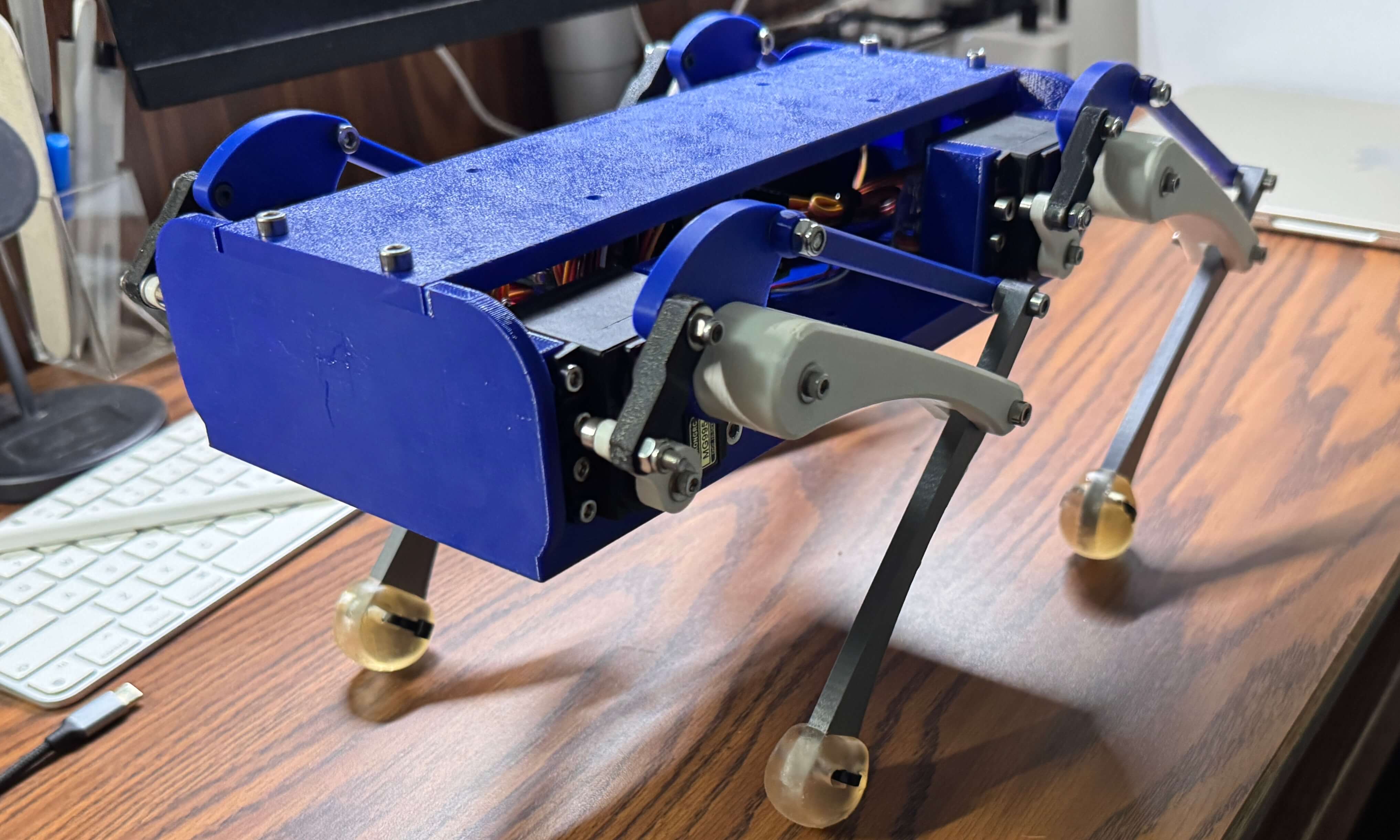
The mechanical structure is derived from the open-source Dingo Robot design, with significant modifications to accommodate the specific servo motors and control electronics.
Design Considerations:
- Servo mounting: Brackets designed for MG995 servo dimensions, ensuring rigid mounting and minimal backlash
- Wire and board management: Integrated mounting holes for Arduino and Raspberry Pi; dedicated recessed slots for IMU sensor placement
- Modularity: Leg assemblies can be easily removed for maintenance or replacement
The robot features a symmetric four-legged design with two degrees of freedom per leg: one for hip rotation (forward/backward swing) and one for knee flexion/extension. This 8-DOF configuration provides sufficient mobility for basic walking gaits while keeping the computational complexity manageable for real-time control on Arduino.
Hardware Components
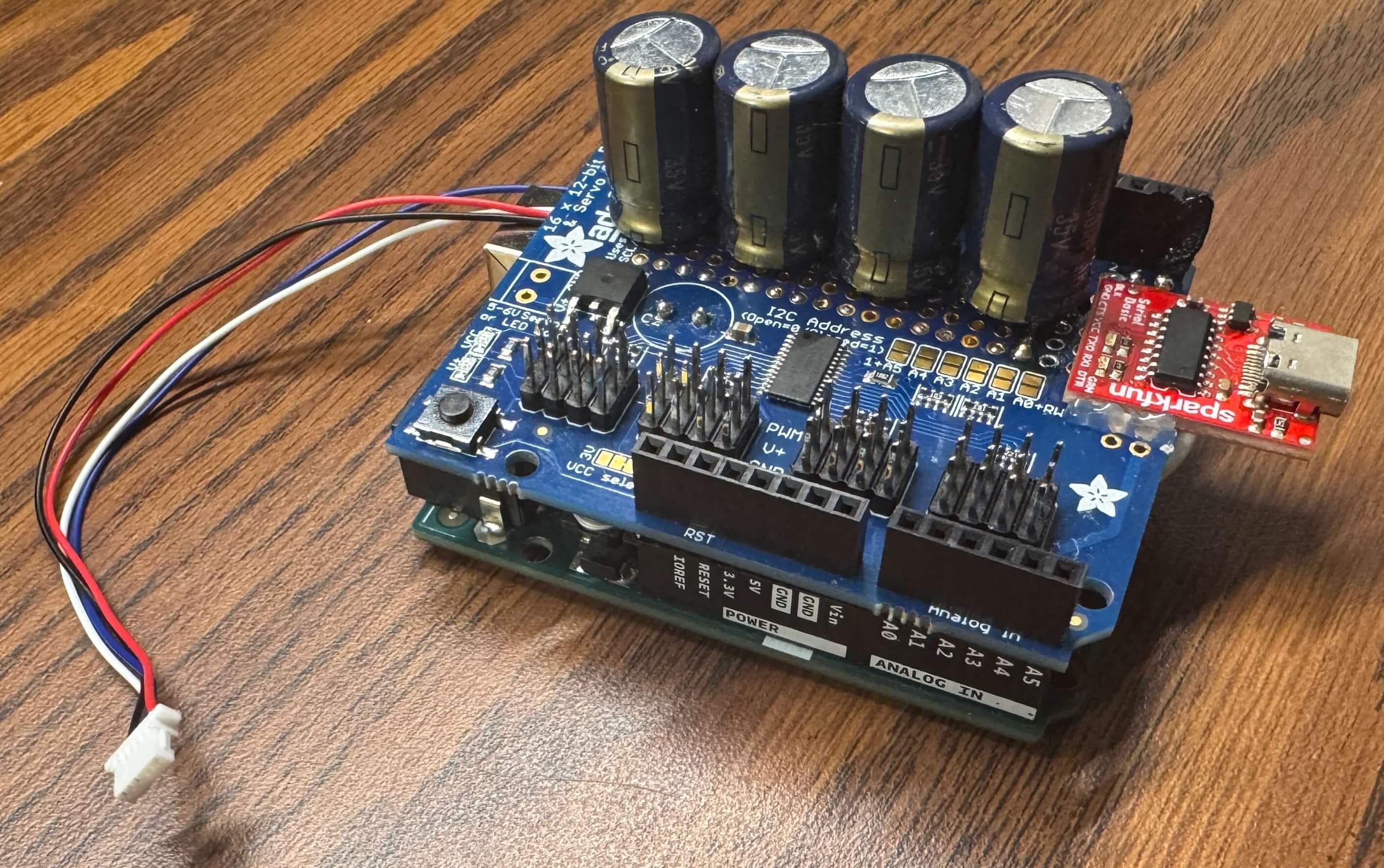
The quadruped robot uses eight MG995 servo motors driven by a PCA9685 PWM controller. A WT901CM 9-axis IMU provides orientation and motion feedback for balance and gait stabilization.
Power is supplied through a 5 V, 3 A USB-C source, with four parallel 1000 µF capacitors to buffer transient servo currents. Future revisions will adopt a USB-PD trigger and high-current buck converters to provide increased input power and regulate the system supply to 7.2 V.
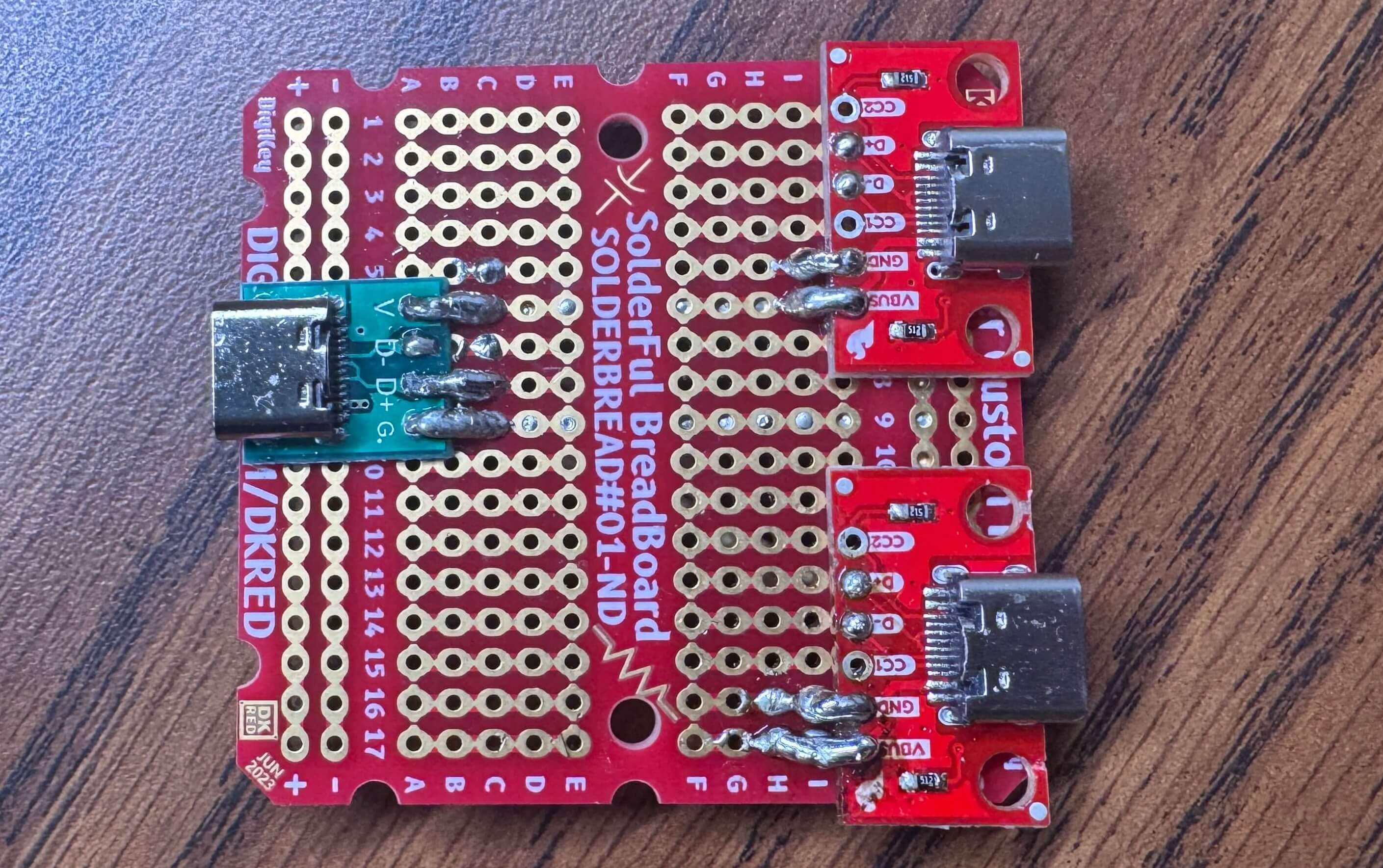
To minimize cabling and isolate power from data, a CH340C USB-to-UART module is integrated on the control board. Three USB-C breakout boards are combined so that power (VCC/GND) is taken from one USB-C port while differential data lines (D+/D−) are taken from another. This configuration enables a single-cable interface for both power delivery and serial communication, and supports future off-board reinforcement-learning control where target joint angles are streamed from a host computer.
Forward and Inverse Kinematics
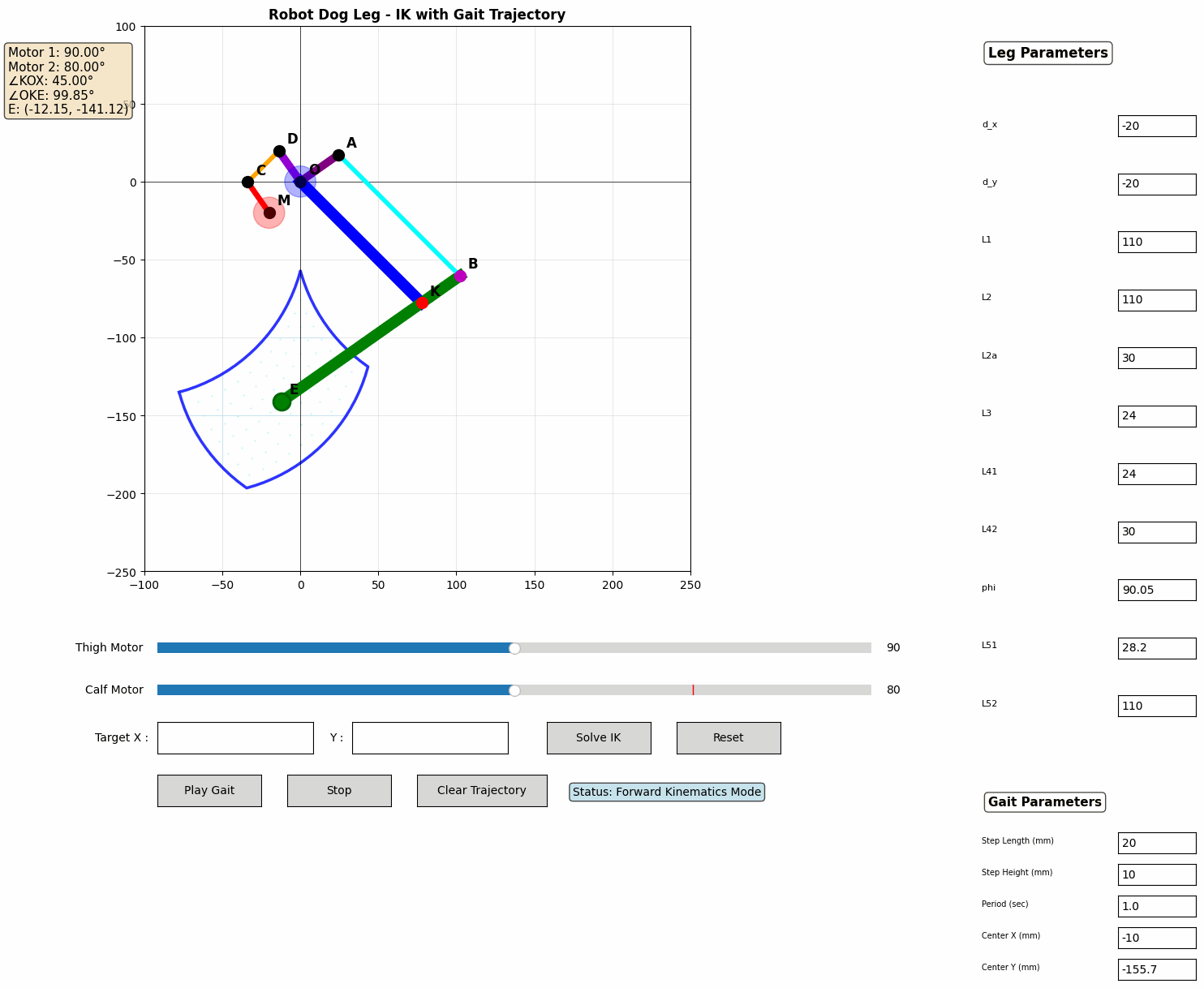
A unified Python interface has been developed for analyzing and controlling the robot dog’s leg kinematics. The leg employs a five-bar linkage mechanism where the calf motor is placed inside the body with motion transmitted through linkages, thereby reducing leg weight and facilitating center of gravity stabilization.
Forward Kinematics
Given two motor angles, the forward kinematics solver calculates:
- Complete joint positions (O, K, D, A, B, E) throughout the mechanism
- Foot endpoint position E in Cartesian coordinates
- Key output angles: thigh angle ∠KOX and knee angle ∠OKE
The coupled parallel linkage is handled through sequential circle-circle intersection solving, with crossing detection implemented to select mechanically valid configurations and avoid link interference.
Inverse Kinematics
A desired foot position (x, y) is taken as input, and the required motor angles are computed by the IK solver. Numerical optimization (Nelder-Mead method) with multiple initial guesses is employed, where joint limits (Motor 1: 60–120°, Motor 2: 60–100°) are respected and solutions with sub-millimeter accuracy are returned.
Gait Trajectory Generation
Parametric gait trajectory generation is included with configurable parameters:
- Step length and height for different terrain requirements
- Gait period/frequency for walking speed control
- Center position for nominal stance adjustment
A swing-stance pattern drives locomotion: during the swing phase (50% of cycle), the foot is lifted and moved forward in an arc; during the stance phase, it is pushed backward along the ground to propel the body forward.
Future Development Roadmap
Phase 1 — ROS Integration
Migrating control architecture to ROS will provide:
- Modular software design: Separate nodes for kinematics, gait generation, sensors, and actuators
- Simulation-to-reality pipeline: Test algorithms in Gazebo before hardware deployment
- Visualization tools: RViz for real-time state monitoring and debugging
- Standardized interfaces: Easy integration of additional sensors (cameras, LIDAR)
The Arduino will serve as a low-level hardware abstraction layer, communicating with a higher-level ROS master (such as a Raspberry Pi or laptop) via rosserial.
Phase 2 — MuJoCo Simulation and Reinforcement Learning
MuJoCo Physics Engine offers:
- Accurate contact dynamics for legged locomotion
- Fast simulation for training data generation
- Differentiable physics for policy gradient methods
Reinforcement Learning Approach:
- Goal: Train a policy that maps IMU readings and terrain information to optimal foot placements
- State space: Body orientation, angular velocities, leg joint positions, contact states
- Action space: Desired foot positions (IK converts to joint commands)
- Reward function: Forward velocity, energy efficiency, stability metrics
- Algorithms: PPO (Proximal Policy Optimization), SAC (Soft Actor-Critic)
The trained policy will enable terrain adaptation (slopes, stairs, uneven ground), robust locomotion recovery from significant disturbances, and energy-optimized gaits more efficient than hand-tuned patterns.
Project Impact and Learning Outcomes
This project demonstrates the integration of multiple engineering disciplines:
- Mechanical Engineering: CAD modeling, 3D printing, mechanism design, structural analysis
- Electrical Engineering: Servo motor control, I²C protocols, sensor integration, power electronics
- Computer Science: Embedded programming, control algorithms, real-time systems, coordinate transformations
- Control Theory: PID tuning, inverse kinematics, trajectory planning, dynamic stability